FACILITY & EQUIPMENT / LAS VEGAS

Substantial capacity. Every detail considered.

A large-scale lyophilization platform, supported by coordinated filling, stoppering, capping and material handling. Explore the documented equipment configuration.

5.5 m²

Nominal lyophilization area

54 L

Tray liquid load · 10 mm depth

21,000+

Ø16 mm · 2 mL vial loading

180–200

Vials/min · filling machine rating

DESIGNED INTO PROJECT PLANNING

Make capacity part of the solution.
Not a production bottleneck.

Our substantial lyophilizing capability supports large tray and vial batches. During technical review, loading, drying cycle, filling and capping are assessed together to help prevent bottlenecks—not just move them between process steps.

Figures below are supplier-documented machine specifications, not measured plant output or guaranteed turnaround. Actual project capacity depends on material, loading format, cycle and agreed scheduling.

The documented equipment configuration

Download capability sheet
01

LYOPHILIZATION

Stoppering vacuum freeze dryer

5.5 m²-class lyophilization platform · ZLFD-50G

54 LTray liquid load at 10 mm depth
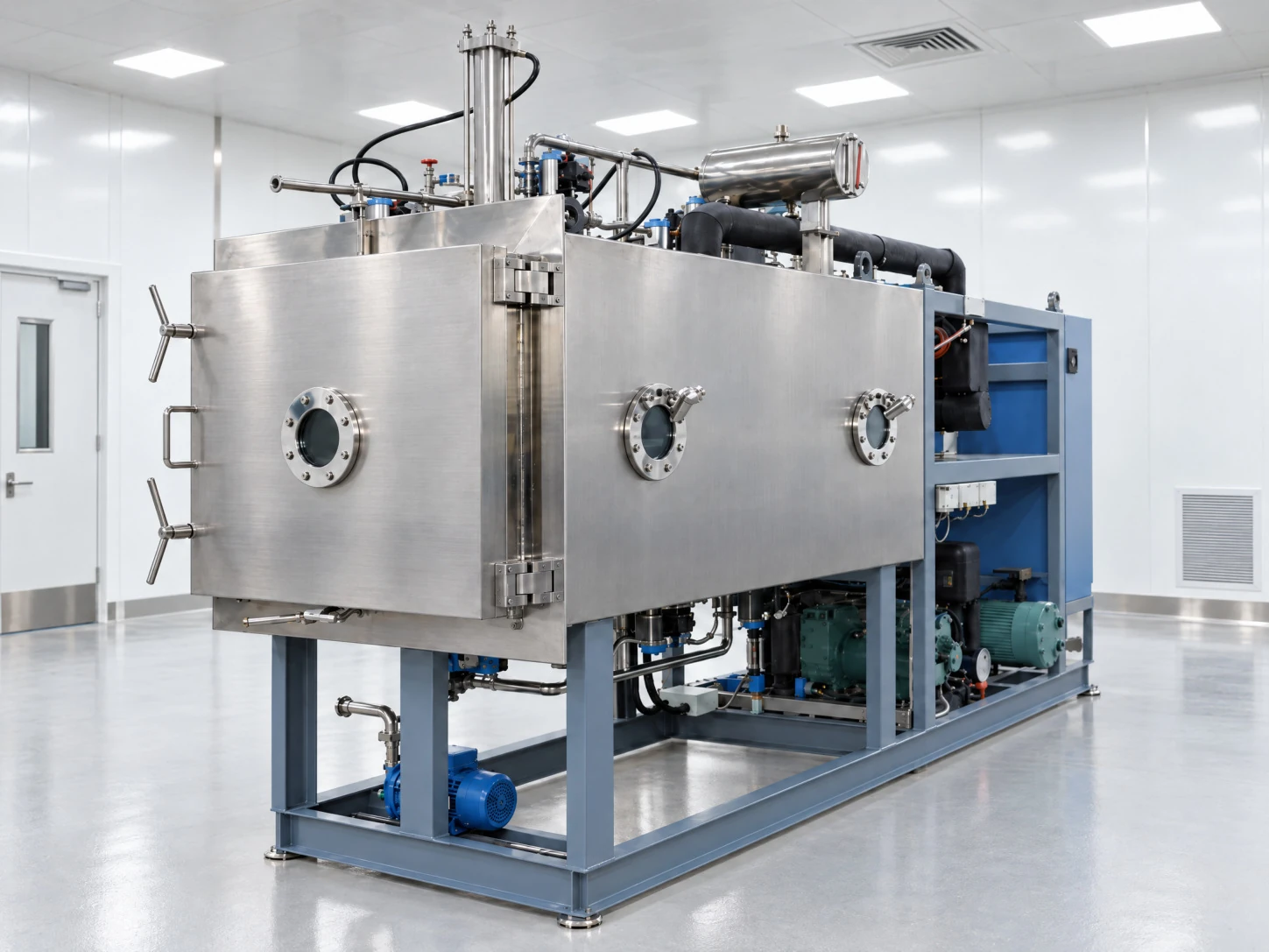
Stoppering vacuum freeze dryer pictured in the PMG Sciences services deck
Documented specifications
Nominal drying area
5.5 m²
Dimensional effective shelf area
5.4 m²
Shelf configuration
5 working shelves + 1 temperature-compensating shelf
Shelf dimensions
1,200 × 900 mm
Shelf spacing
90 mm
Tray liquid loading
54 L at 10 mm material depth
Small-format vial loading
≥21,000 vials · 2 mL nominal vial size · Ø16 mm
Larger-format vial loading
≥10,800 vials · 10 mL nominal vial size · Ø22 mm
Condenser water capture
≥100 kg
Minimum condenser temperature
≤−70 °C · no-load
Shelf temperature envelope
−50 to +70 °C · no-load, conservative documented range
Shelf temperature uniformity
±1 °C at equilibrium
Ultimate vacuum
≤5 Pa · no-load
Vacuum control range
10–130 Pa
Cooling
Water cooled · approximately 15 m³/h
Defrosting
Water soaking
Chamber and shelves
AISI 304 stainless steel
Installed power
35 kW · not operating power consumption
Electrical supply
3-phase + N + PE · 380 V
Reference dimensions
Approximately 3,800 × 1,600 × 2,500 mm
Reference weight
Approximately 4,500 kg
Controls
Siemens PLC and touch screen · automatic/manual control

Vial figures describe container loading, not liquid fill volume. The supplier lists both 5.5 m² nominal and 5.4 m² effective shelf area. Actual batch suitability depends on material, vial geometry, fill and cycle requirements.

SOURCE: Lyophilizer specification, pages 2–5, 8, 10–11
02

FILLING & STOPPERING

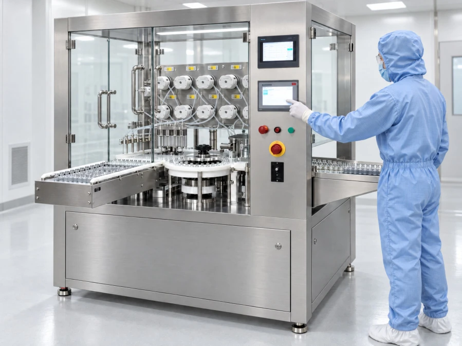
Automatic filling & stoppering machine

Honsimba DHKZ012 · 8-head peristaltic system

180–200Supplier-rated vials per minute
Automatic filling & stoppering machine pictured in the PMG Sciences services deck
Documented specifications
Documented quantity
1 machine
Filling heads
8
Filling method
Peristaltic pump
Rated speed
180–200 vials/min · standardized packaging
Electrical supply
220 V · 50 Hz
Installed power
5 kW
Construction
304 stainless steel frame
Reference dimensions
1,800 H × 1,600 L × 1,300 W mm · excluding hood
Reference weight
Approximately 700 kg
Controls
PLC, touch screen and servo-indexed turntable
Handling
Automatic bottle feeding, filling, stopper placement and outlet

Fill range and accuracy are confirmed at technical review because the supplier document contains inconsistent values. Rated machine speed is not a guaranteed end-to-end production rate.

SOURCE: Filling/capping documentation, pages 1, 3–4
03

CAPPING

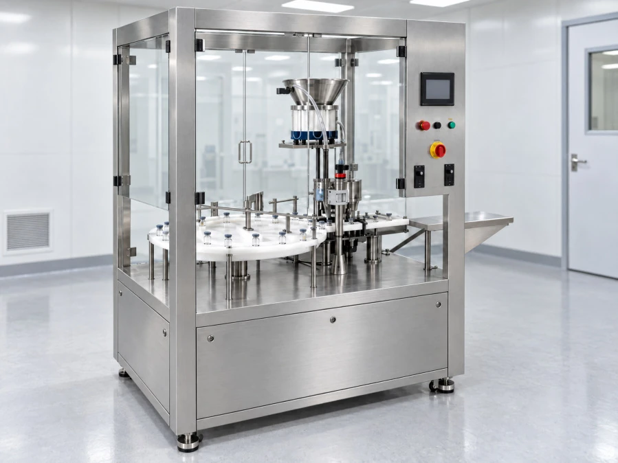
Automatic high-speed capping machine

Honsimba · 8-head configuration

180–200Supplier-rated vials per minute
Automatic high-speed capping machine pictured in the PMG Sciences services deck
Documented specifications
Documented quantity
1 machine
Capping heads
8
Rated speed
180–200 vials/min · standardized packaging
Electrical supply
220 V · 50 Hz
Installed power
5 kW
Construction
304 stainless steel frame
Reference dimensions
1,400 H × 1,600 L × 1,300 W mm
Reference weight
Approximately 500 kg
Controls
PLC, touch screen and servo-indexed turntable
Handling
Automatic cap placement, locking and bottle outlet

Final bottle and cap compatibility is reviewed before project acceptance. Filling and capping rates are separate machine ratings, not additive throughput.

SOURCE: Filling/capping documentation, pages 7–8
04

AIR HANDLING

Laminar flow hood

Supporting equipment for the filling configuration

H14Documented filter specification
Documented specifications
Documented quantity
1 hood
Filter
H14 filter specified by supplier
Construction
304 stainless steel
Installed power
0.5 kW
Single-motor noise
<65 dB
Features
Differential pressure meter and independently controlled LED lighting

The filter specification is an equipment detail, not a claim about the operating environment. Ambiguous dimensions and airflow entries are not published.

SOURCE: Filling/capping documentation, page 6
05

MATERIAL HANDLING

Buffer tank

Material holding support · S31603 stainless steel

50 LDocumented total vessel volume
Documented specifications
Documented quantity
1 tank
Total volume
0.05 m³ · 50 L gross
Material
S31603 stainless steel
Documented conditions
Atmospheric pressure and ambient temperature
Connections
Feed, discharge, vent, spare and cleaning ports

Gross vessel volume is not a stated usable working volume. Project-specific working load is confirmed during technical review.

SOURCE: Filling/capping documentation, pages 11–13

INTEGRATED SUPPORTING SYSTEMS

The systems behind the process.

Refrigeration compressor

1 BITZER S6H-16.2Y two-stage compressor serving the shelf/condenser refrigeration configuration.

Cooling-water chiller

1 supplier-designated 15P chiller. Thermal cooling output is not stated in the supplied document.

Vacuum pump

1 two-stage rotary-vane pump with POSIFA vacuum instrumentation. Pump flow rate is not stated.

Thermal-fluid circulation

1 Grundfos circulation pump with low-viscosity silicone-oil heat transfer fluid and a 15 kW heater.

Control & monitoring

Siemens PLC/touch screen on the dryer; PT-100 temperature sensing and automated/manual controls.

Refrigeration components

Danfoss valves and protection controls; ZOER oil/gas-liquid separation components and LR/REFCO pressure instrumentation.

Las Vegas, Nevada

4300 W Tropicana, Building C, Las Vegas, NV 89103

Discuss a project

LET’S DEFINE WHAT’S NEXT

Your next project
starts here.

Bring us your material, requirements and goals.
We’ll start with the right questions.

Request a Project Consultation